ENG3014 · Communication Systems

Scroll

Part 1

Introduction to communications

Communication waveforms are time-varying signals. The ability to communicate at a high datarate basically requires a higher frequency of transmission.

x(t)=Acos⁡(2πft) x(t) = A\cos(2\pi f t)

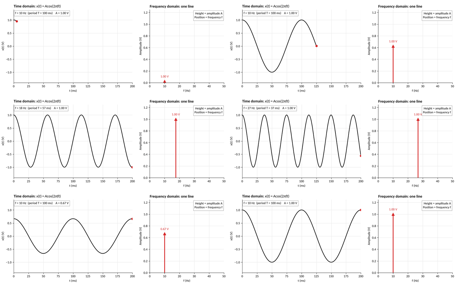
In frequency domain, one sine wave is one line: its position is ff, its height is AA.

A sine wave in time and its single spectral line; the line moves as the frequency changes and shrinks as the amplitude changes

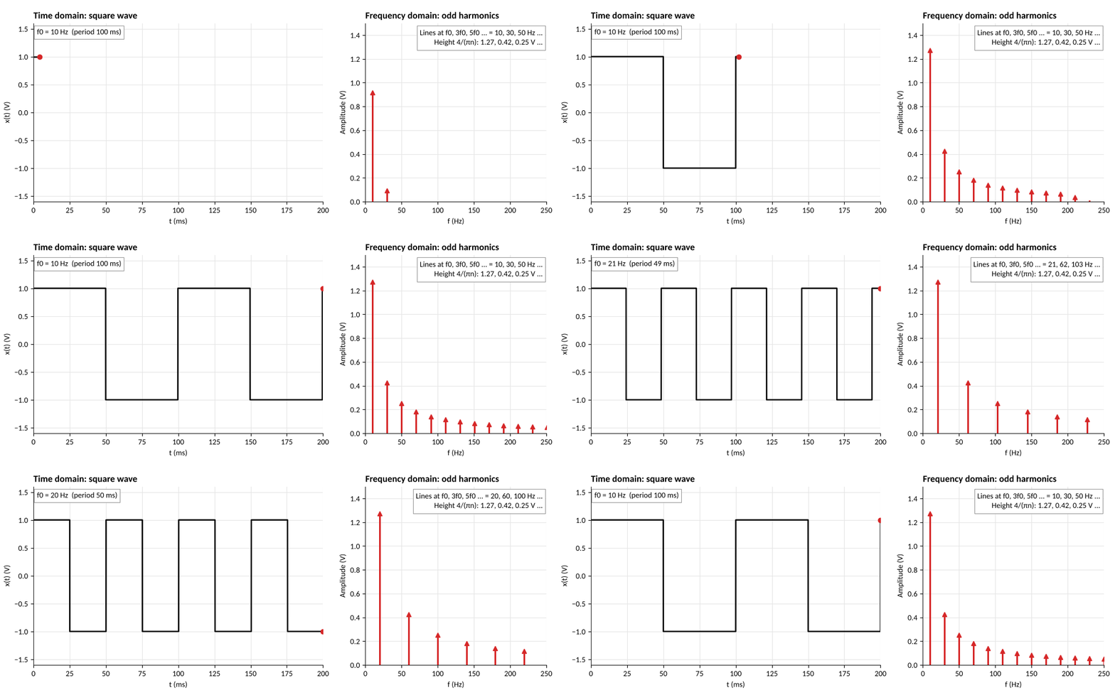
Non continuous changes in signals, e.g. a switch from 0 to 1, cannot be described by a finite number of sin functions, and are instead approximated.

x(t)=4π∑n odd1nsin⁡(2πnf0t) x(t) = \frac{4}{\pi}\sum_{n\ \text{odd}} \frac{1}{n}\sin(2\pi n f_0 t)

Faster data, wider spectrum.

A square wave in time and its comb of odd harmonics, which spreads out as the square wave speeds up

Fourier transform probes for each frequency

X(f)=∫−∞∞x(t) e−j2πft dt X(f) = \int_{-\infty}^{\infty} x(t)\, e^{-j2\pi f t}\, dt

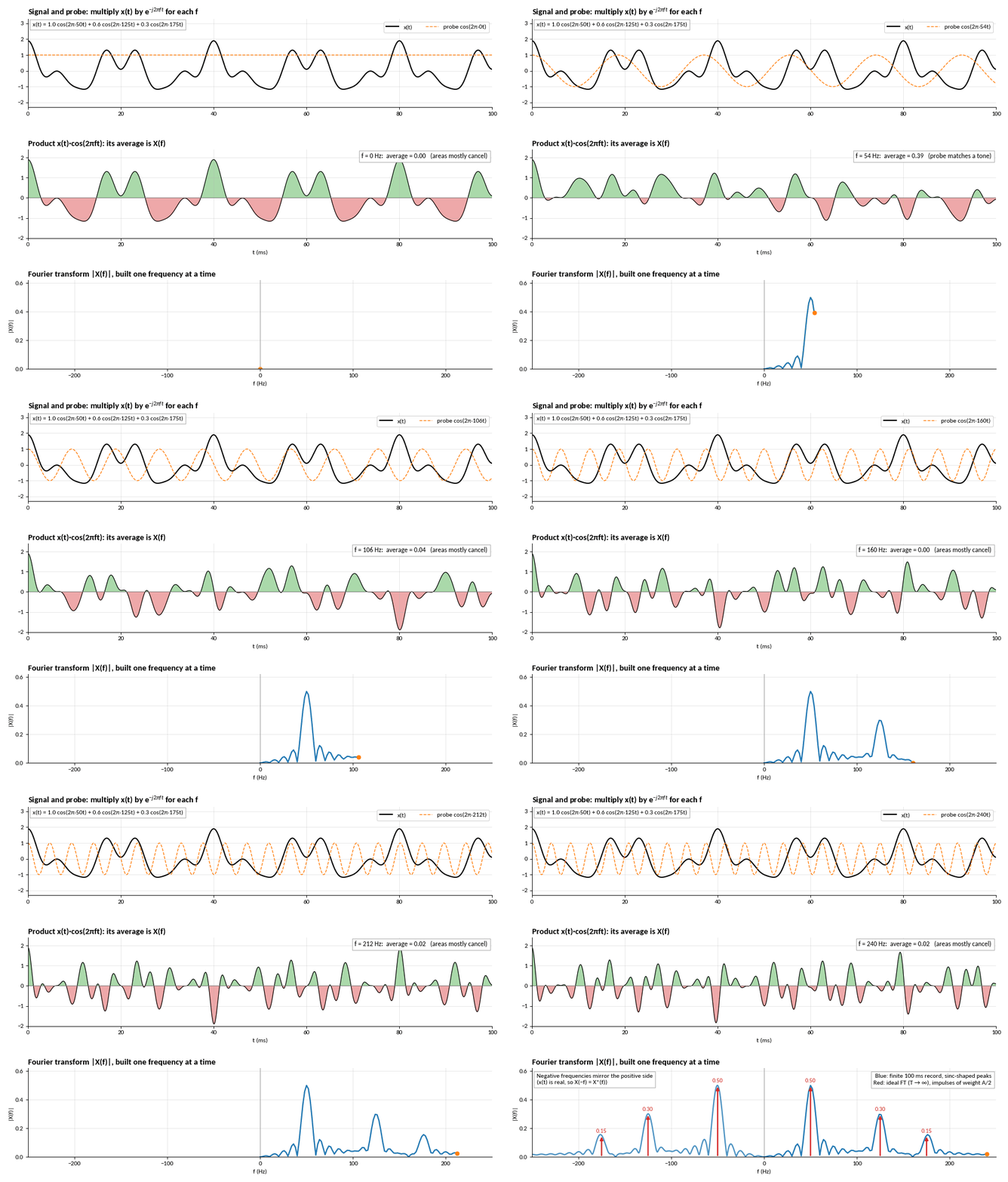
Multiply by a probe at ff and average: the result is large only if ff is in the signal.

A three-tone signal multiplied by a sweeping probe; the averaged product builds the Fourier transform with peaks at plus and minus 50, 125 and 175 Hz

Part 2

Wireless Carriers and Modulation

Modulating a carrier's amplitude using a message (a time-varying signal) adds positive and negative sidebands

s(t)=[A+μAcos⁡(2πfmt)]cos⁡(2πfct)=Acos⁡(2πfct)+μAcos⁡(2πfmt)⋅cos⁡(2πfct)=Acos⁡(2πfct)carrier+μA2cos⁡ ⁣(2π(fc−fm)t)lower sideband+μA2cos⁡ ⁣(2π(fc+fm)t)upper sideband \begin{aligned} s(t) &= \big[A + \mu A\cos(2\pi f_m t)\big]\cos(2\pi f_c t) \\ &= A\cos(2\pi f_c t) + \mu A\cos(2\pi f_m t)\cdot\cos(2\pi f_c t) \\[0.4em] &= A\cos(2\pi f_c t) \quad \textcolor{#c1d102}{\text{carrier}} \\ &\quad + \frac{\mu A}{2}\cos\!\big(2\pi(f_c - f_m)t\big) \quad \textcolor{#c1d102}{\text{lower sideband}} \\ &\quad + \frac{\mu A}{2}\cos\!\big(2\pi(f_c + f_m)t\big) \quad \textcolor{#c1d102}{\text{upper sideband}} \end{aligned}

A 400 Hz carrier and a 10 Hz message: lines at 390, 400 and 410 Hz.
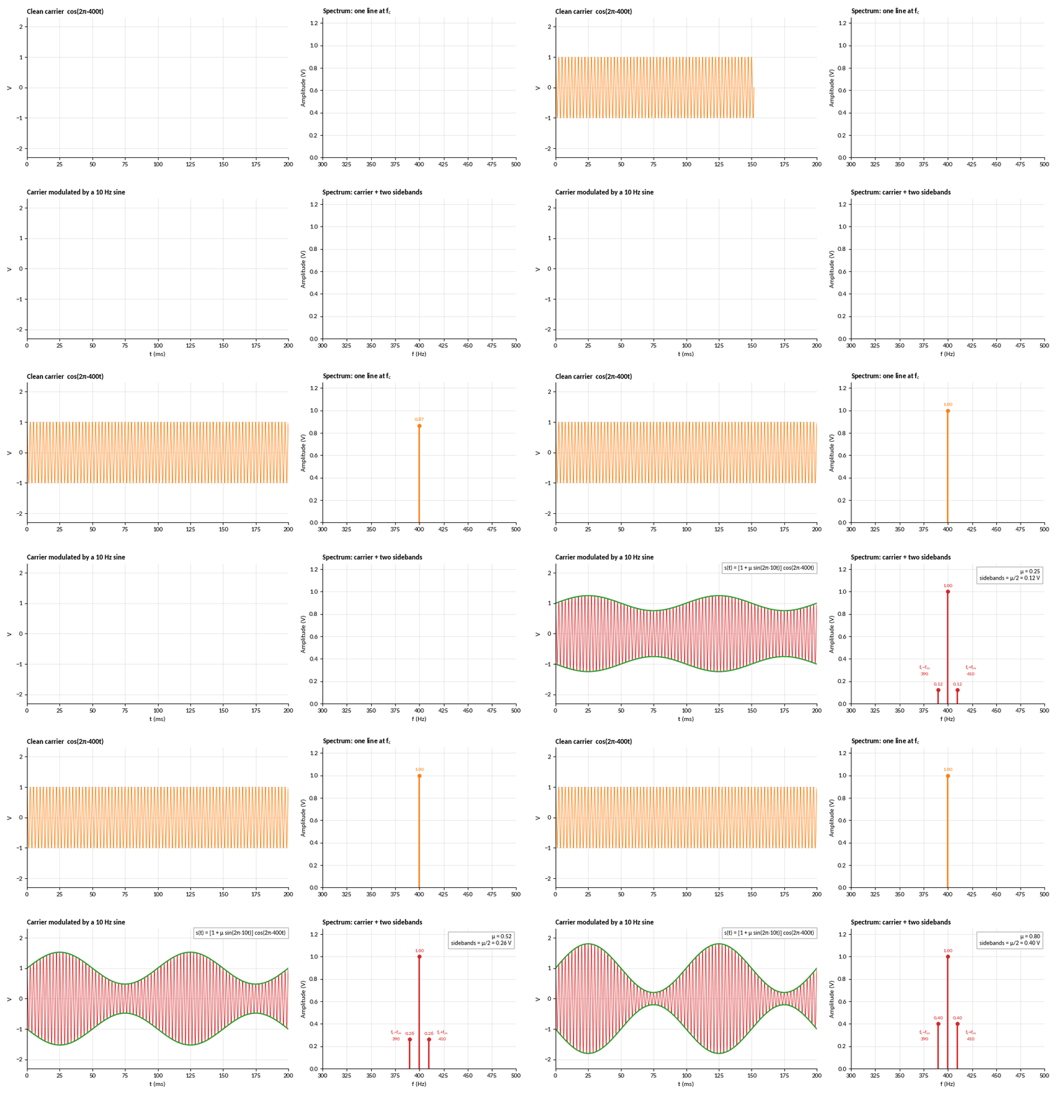
A clean 400 Hz carrier with one spectral line, then the carrier modulated by a 10 Hz sine with a carrier line and two sidebands

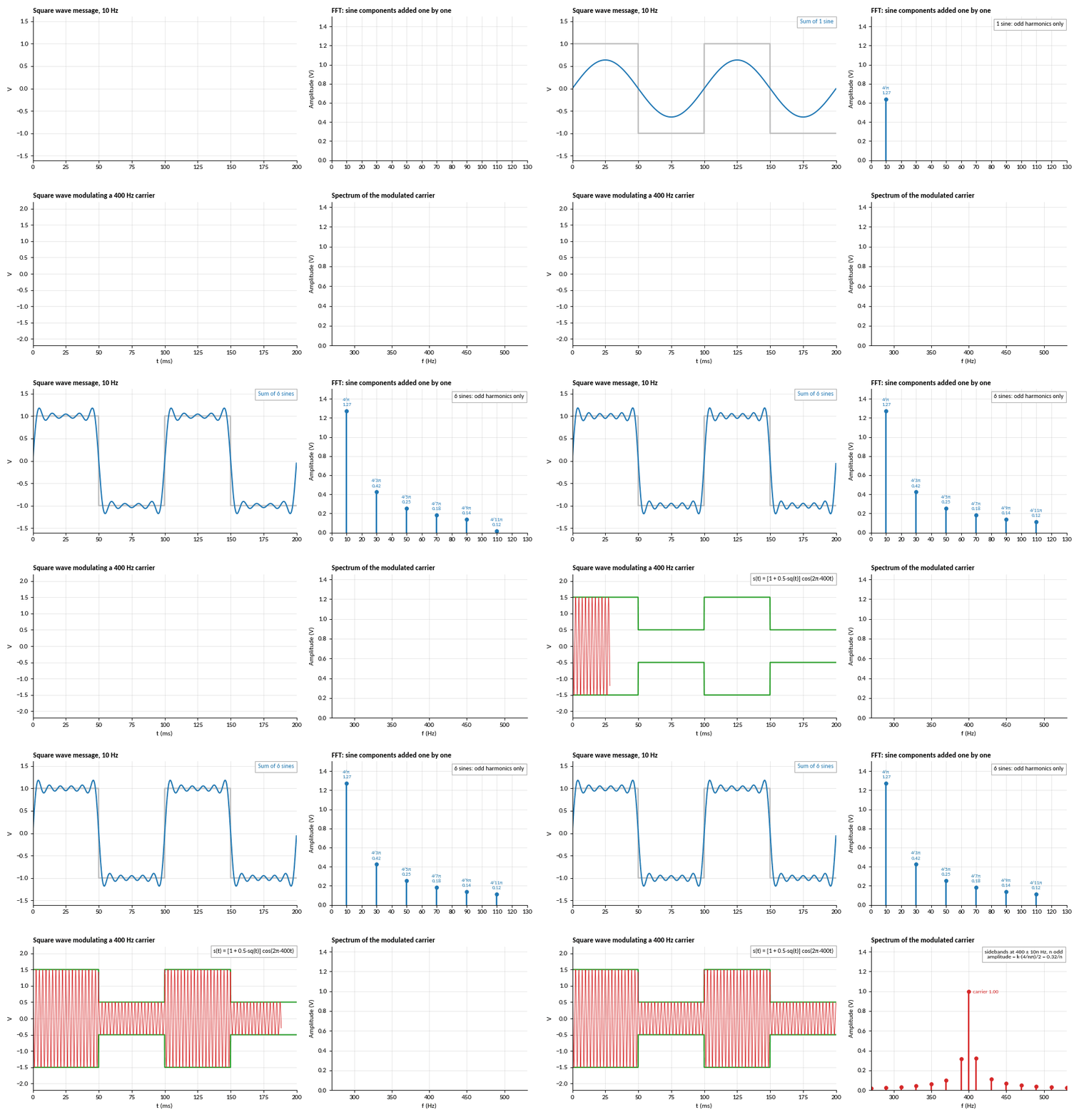
Modulated signals encode their information in the sidebands
BAM=2W B_{AM} = 2W
A 10 Hz square wave and its FFT, then the square wave modulating a 400 Hz carrier and the spectrum around the carrier

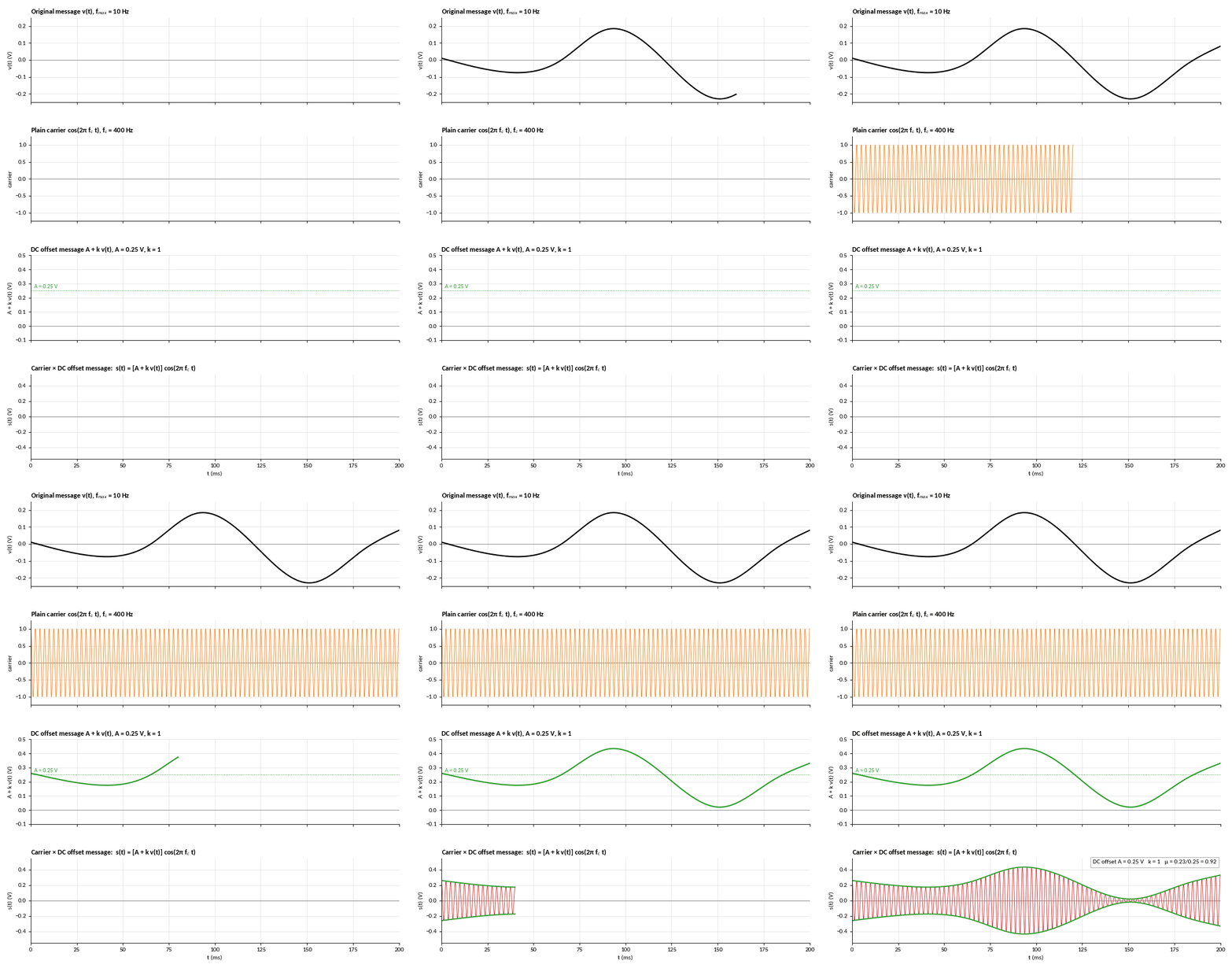
Modulation is DC-offset - for analogue AM, the amplitude is the time-varying data waveform
s(t)=[A+k v(t)]cos⁡(2πfct) s(t) = \big[A + k\,v(t)\big]\cos(2\pi f_c t)
Four stacked plots: the message, a 400 Hz carrier, the message with a 0.25 V DC offset, and their product, the AM signal

When demodulating AM, the envelope recovers the lower frequency information waveform

μ=max⁡∣k v(t)∣A≤1 \mu = \frac{\max\lvert k\,v(t)\rvert}{A} \le 1

Above 1, the envelope crosses zero: over-modulation.
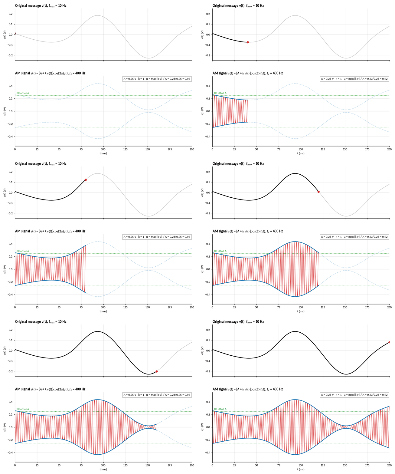
A message and the AM signal it produces, with the envelope following the message around the DC offset, modulation index 0.92

Continuous FM modulates the frequency - this, however, is done by controlling the phase of the carrier

s(t)=Accos⁡ ⁣(2πfct+2πkf ⁣∫0tv(τ) dτ)=Accos⁡ ⁣(2πfct+βsin⁡(2πfmt)) \begin{aligned} s(t) &= A_c\cos\!\Big(2\pi f_c t + 2\pi k_f\!\int_0^t v(\tau)\,d\tau\Big) \\ &= A_c\cos\!\big(2\pi f_c t + \beta\sin(2\pi f_m t)\big) \end{aligned}

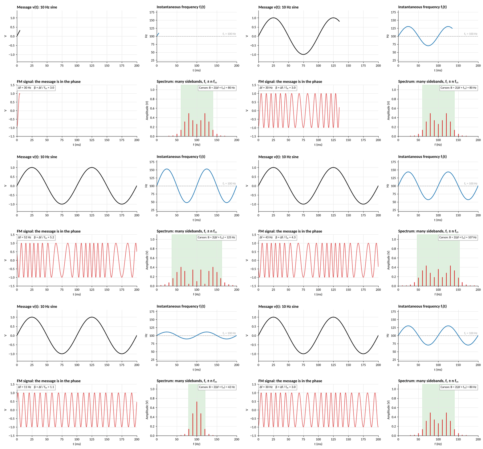
The second line is for a tone, v(t)=cos⁡(2πfmt)v(t) = \cos(2\pi f_m t), with β=Δf/fm\beta = \Delta f / f_m. Constant amplitude, many sidebands. Carson: B≈2(Δf+fm)B \approx 2(\Delta f + f_m).

A 10 Hz message, the FM signal whose cycles bunch and spread with it, its instantaneous frequency, and a spectrum of many sidebands that widens as the deviation grows

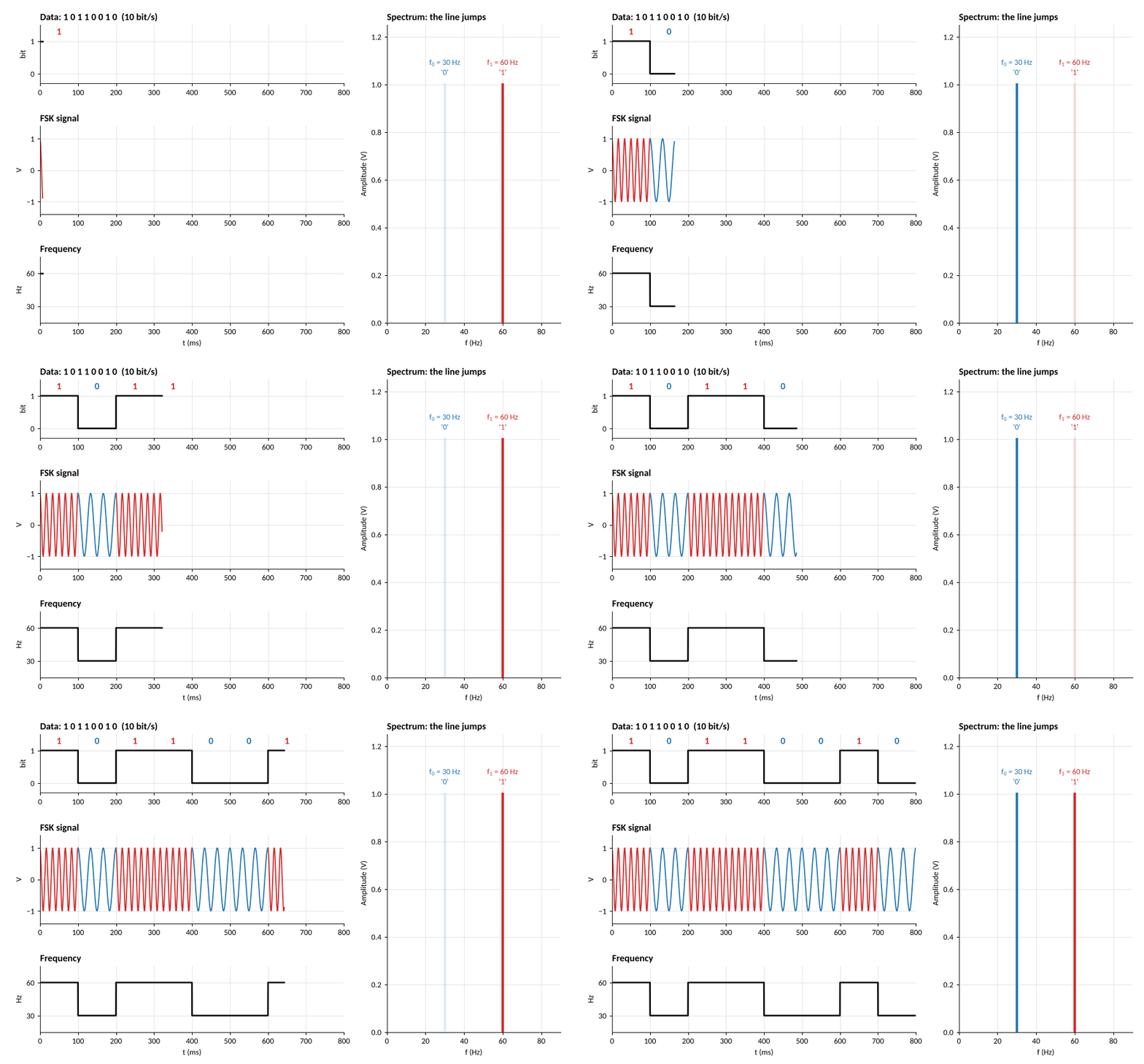
As most information to be transmitted is digital, bits can be encoded as discrete frequencies, i.e. Frequency Shift Keying (FSK)

s(t)={Acos⁡(2πf1t)bit 1Acos⁡(2πf0t)bit 0 s(t) = \begin{cases} A\cos(2\pi f_1 t) & \text{bit } 1 \\ A\cos(2\pi f_0 t) & \text{bit } 0 \end{cases}

f1,0=fc±Δff_{1,0} = f_c \pm \Delta f, and B≈2Δf+2RbB \approx 2\Delta f + 2R_b for bit rate RbR_b.

A bit stream 1 0 1 1 0 0 1 0 and the FSK signal switching between 60 Hz for ones and 30 Hz for zeros, with the spectral line jumping between the two

Part 3

Practical Hardware: Oscillator Phase Noise

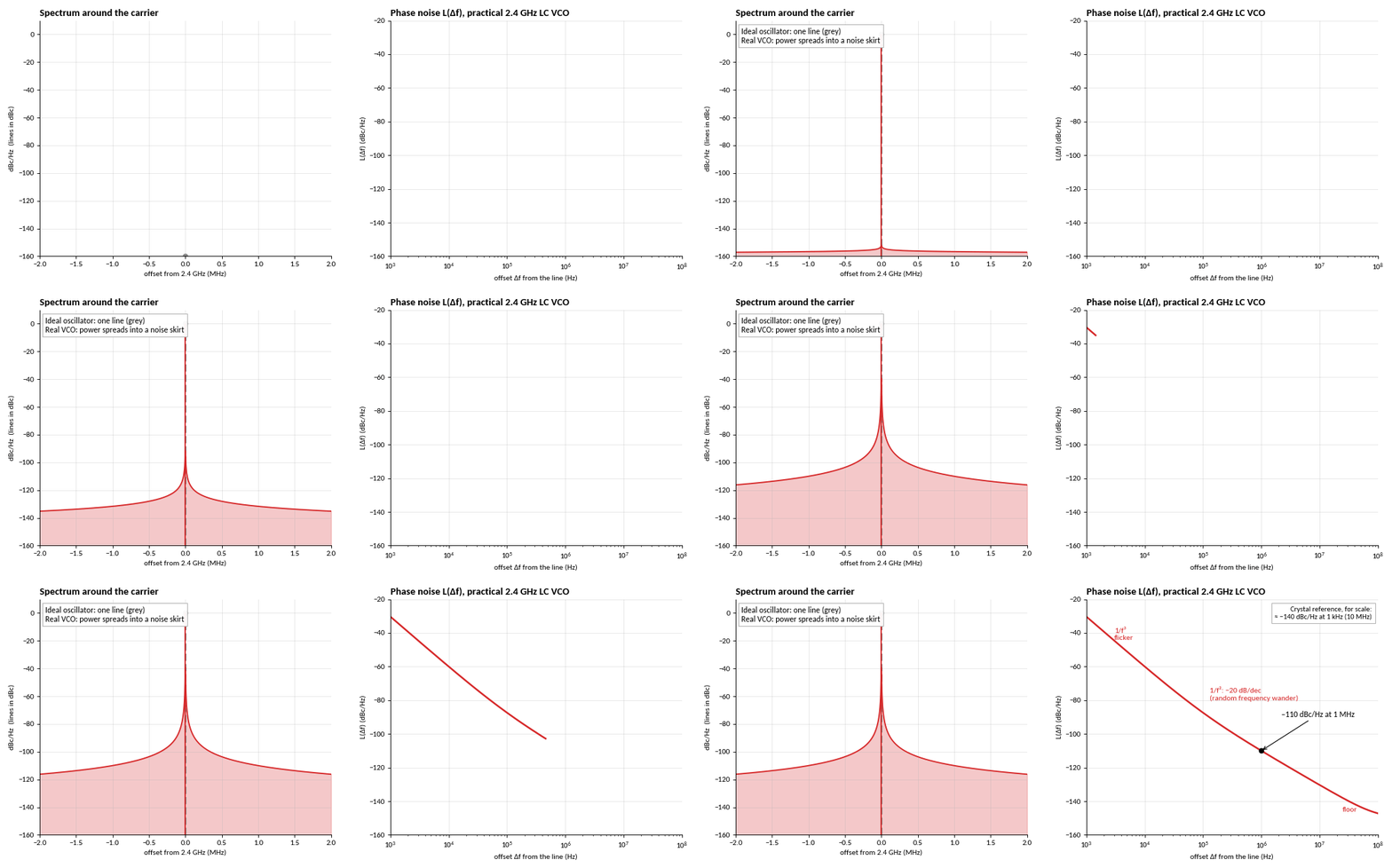
A real oscillator is not a perfect line, there is jitter in its oscillation cycles. Jitter appears as a random shift in frequency with a lower magnitude

L(Δf)=Pnoise in 1 Hz at ΔfPcarrier \mathcal{L}(\Delta f) = \frac{P_{\text{noise in 1 Hz at }\Delta f}}{P_{\text{carrier}}}

Measured in dBc/Hz.

The spectrum around a 2.4 GHz carrier spreading from a single line into a noise skirt, and the phase noise of a practical LC VCO against offset frequency

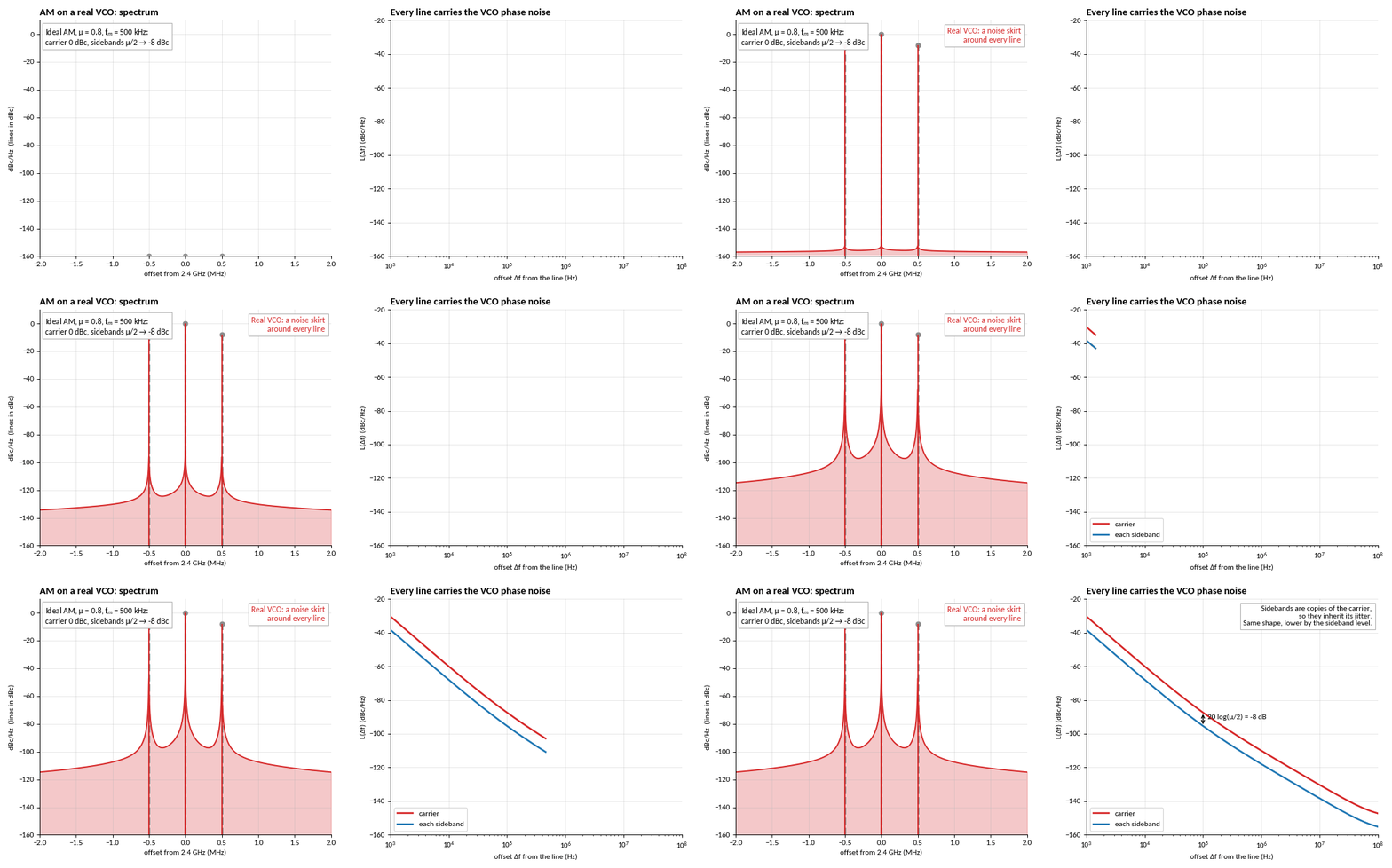
Such jitter transfers to the modulated signal; the sidebands inherit the carrier's phase noise
20log⁡10 ⁣(μ2)≈−8 dB(μ=0.8) 20\log_{10}\!\left(\frac{\mu}{2}\right) \approx -8\ \text{dB} \quad (\mu = 0.8)
AM on a real VCO: the carrier and both sidebands each carry a noise skirt, with the sideband phase noise 8 dB below the carrier's

Part 4

Wireless channels

Radiated electromagnetic power spreads over a growing sphere around the TX antenna

Pr=Pt Gt Gr(λ4πd)2 P_r = P_t\, G_t\, G_r \left(\frac{\lambda}{4\pi d}\right)^{2}

−6 dB every time the distance doubles.
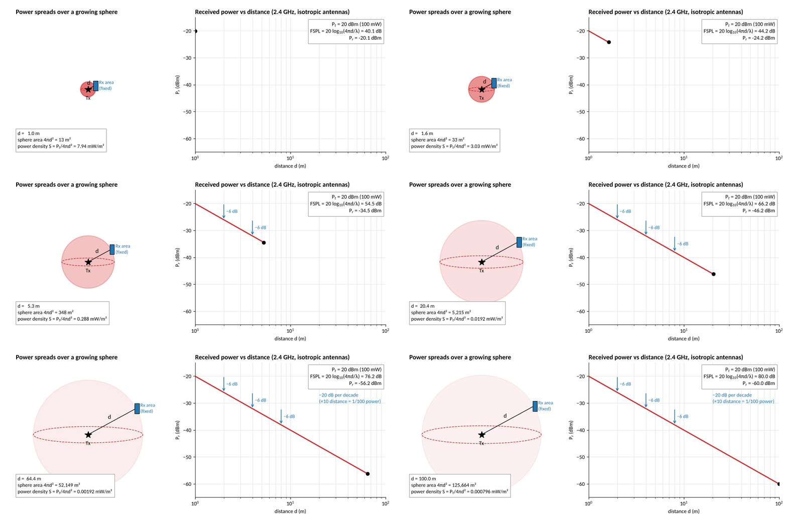
A sphere of radiated power growing around a transmitter while a fixed receiver area collects less of it; received power falls in a straight line against log distance

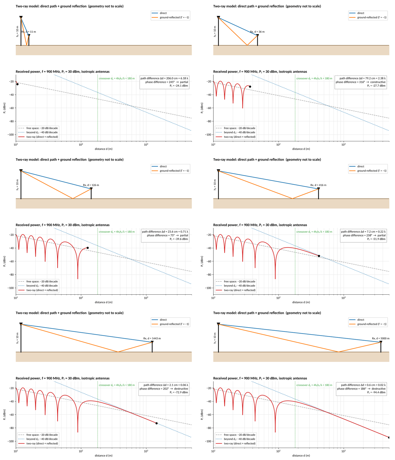
Over ground, reflection causes periodic changes

Pr≈Pt Gt Gr ht2 hr2d4 P_r \approx P_t\, G_t\, G_r\, \frac{h_t^2\, h_r^2}{d^4}

Direct and reflected waves add and cancel up close, then −40 dB per decade beyond dc=4hthr/λd_c = 4h_t h_r/\lambda.

Two-ray scene with direct and ground-reflected rays, and received power against distance showing interference nulls then a 40 dB per decade fall

Motion shifts the frequency: Doppler and Fading

fr=fc±fDfD=vc fc \begin{gathered} f_r = f_c \pm f_D \\ f_D = \frac{v}{c}\, f_c \end{gathered}

Approaching: higher. Receding: lower. A car at 30 m/s shifts 2.4 GHz by 240 Hz.
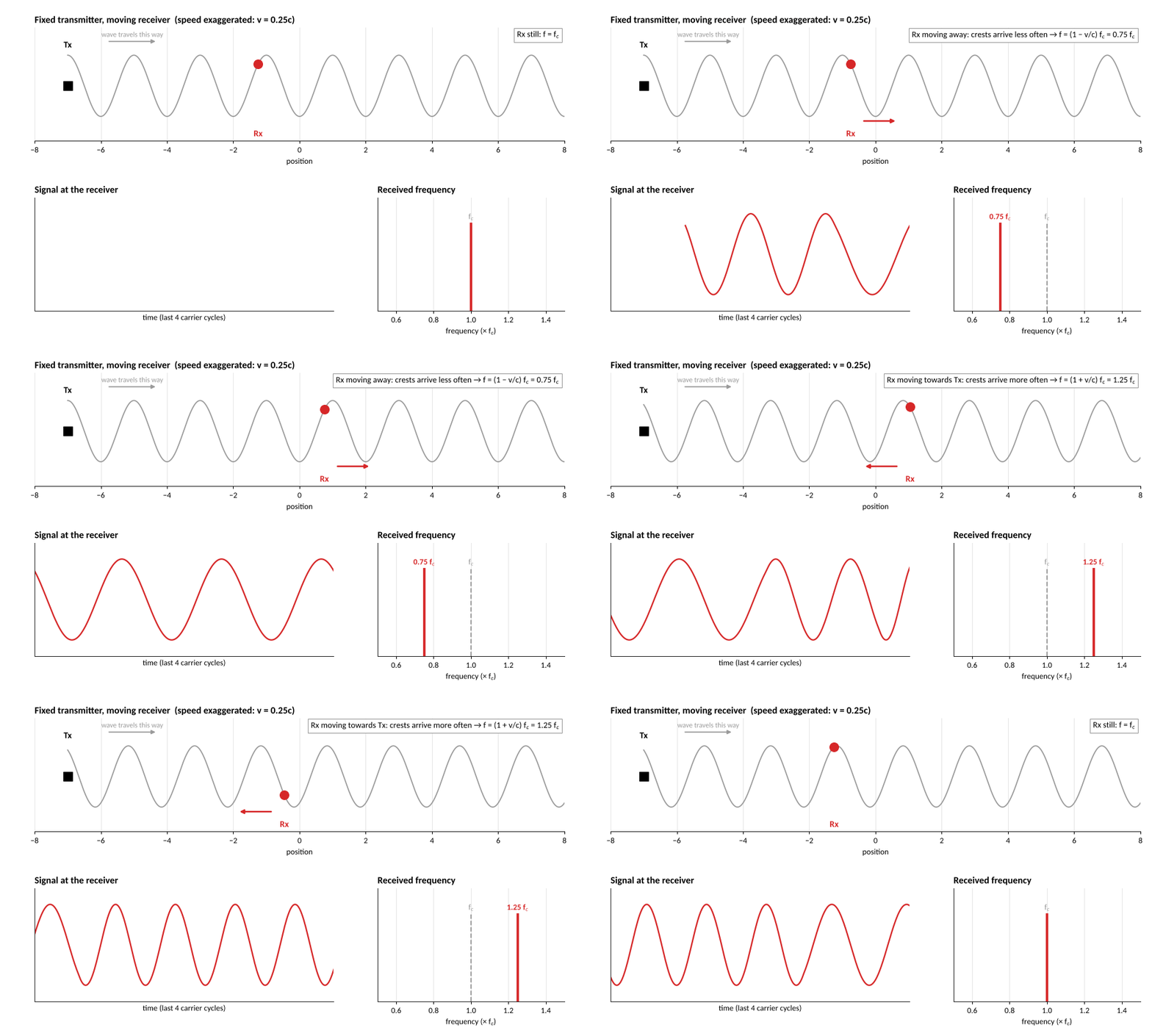
A fixed CW transmitter and a moving receiver: moving away, the receiver sees a lower frequency (0.75 fc); moving towards the transmitter, a higher frequency (1.25 fc)